




-
 Courier delivery
-
 DHL Courier delivery
-
 Warranty 1 year
-
 Free 30-Day returns

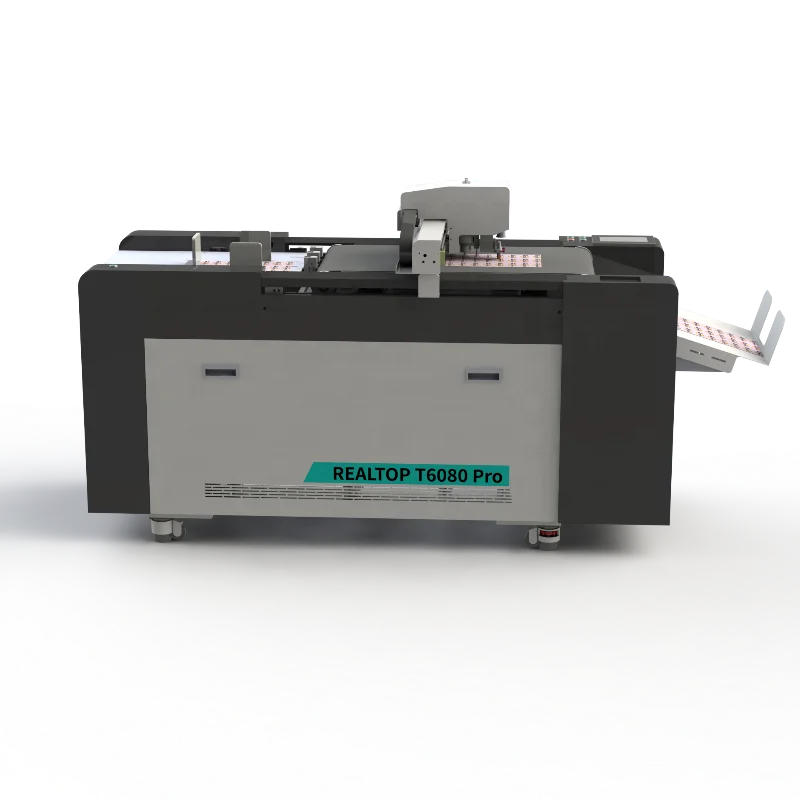
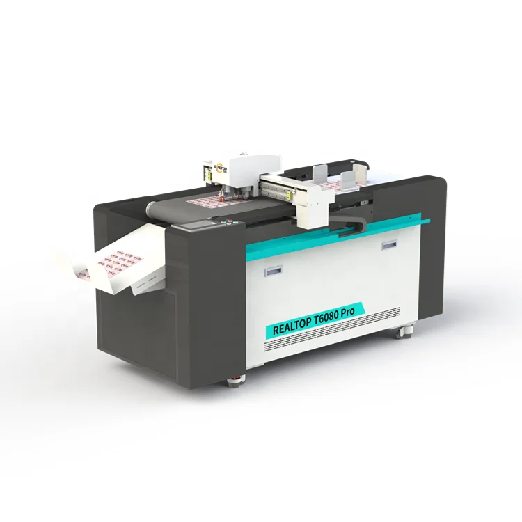
Design-to-material matching — Every RTT6080 flatbed table leaves our Jinan facility with a tool head list mapped to your specific substrate, verified by a physical sample cut before the crate closes.
Technical Specifications
| Parameter | Value |
|---|---|
| Model | RTT6080 / RTT6080 Pro |
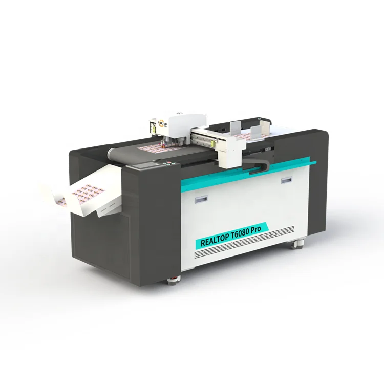
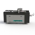
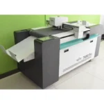
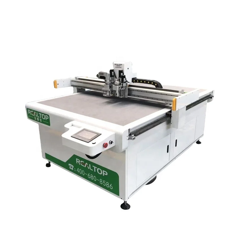
| Product Type | CNC Flatbed Digital Cutting Table |
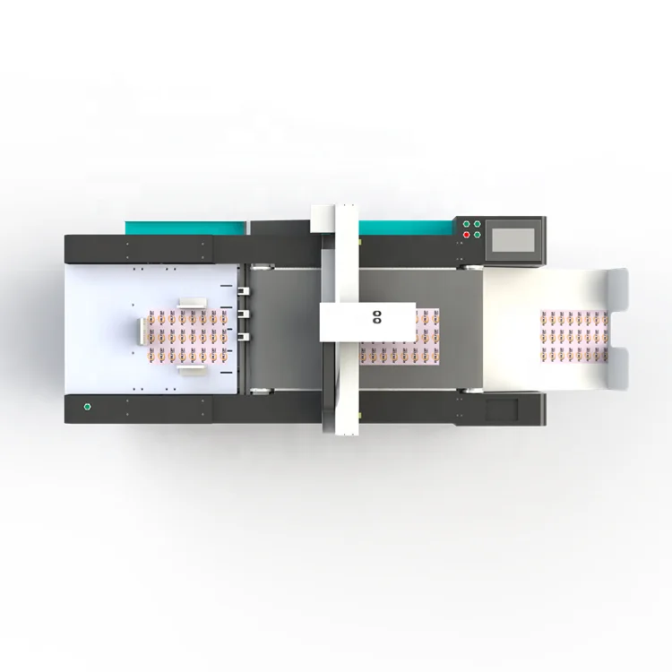
| Max Working Area | 600 mm × 800 mm |
| Cutting Thickness (RTT6080) | ≤ 2 mm |
| Cutting Thickness (RTT6080 Pro) | ≤ 5 mm |
| Max Cutting Speed | 1500 mm/s (basis not stated in source) |
| Positioning Accuracy | 0.05 mm |
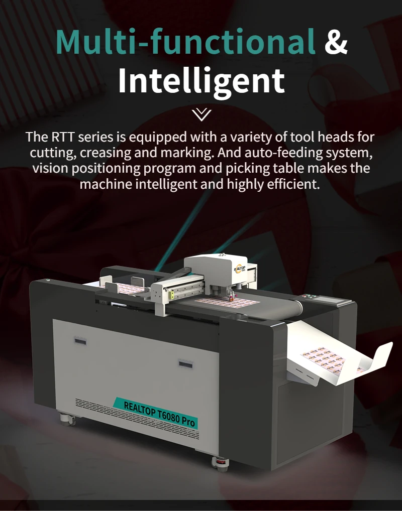
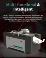
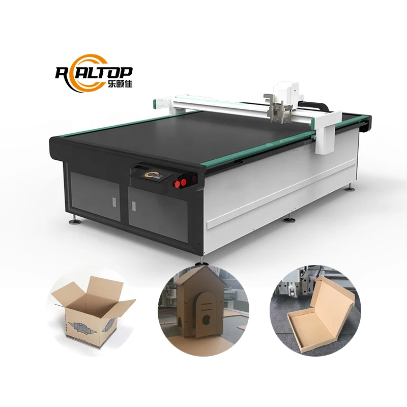
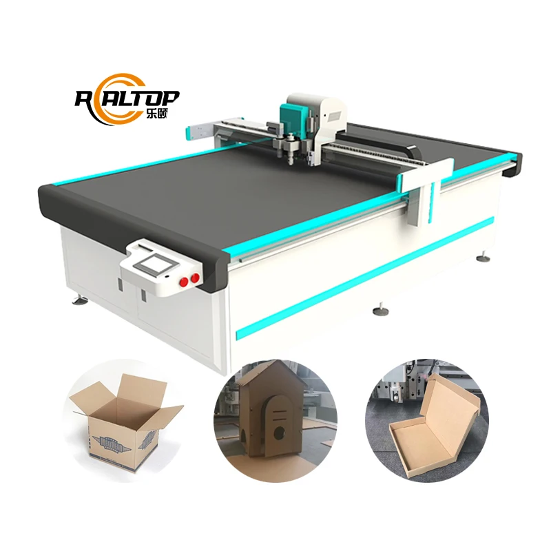
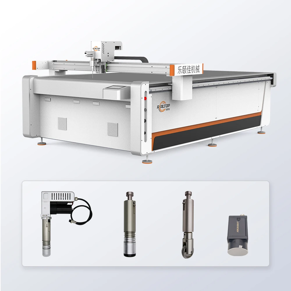
| Tool Head Options | Cutting tool, kiss cutting tool, creasing tool, high speed oscillating knife (Pro), CCD camera |
| Supported File Formats | DXF, PLT, PDF, AI |
| Data Transfer | Ethernet port |
| Rated Power | 3.2 kW |
| Voltage & Frequency | 220V / 380V, 50Hz |
| CCD Camera | Included |
| Key Features | Multi-tool configuration on single table, CCD contour recognition, software nesting compatibility to be confirmed |
Application Suitability
| Application | Material or Output |
|---|---|
| Packaging and carton sample making | A4 and small-format corrugated board, folding carton stock, greyboard |
| Advertising and signage prototyping | Self-adhesive vinyl, thin PVC foam board, magnetic sheet |
| Gasket and composite prototyping | Aramid fiber, cork-rubber sheet, PTFE film, thin non-asbestos board |
| Label and sticker production | Paper-backed label stock, kiss-cut vinyl decals, reflective film |
| Small-format textile sampling | Woven cotton, PU leather, technical textile swatches |
Why "Max Cutting Speed" Means Nothing Without Your Material in the Clamps
A rated speed is only valid on the substrate you actually run, not on a generic test sheet.
When a buyer reads 1500 mm/s on a spec sheet and takes it as gospel for daily output planning, the gap between expectation and reality shows up on the first production shift. I remember configuring a vibrating knife system for an automotive floor mat order in the Middle East. The rated throughput assumed a standard EVA foam, but the customer was running high-density XPE that forced the blade to decelerate on every corner. Actual output dropped to roughly half. On a compact format table like the RTT6080, the same principle applies — only at this scale the consequence is wrong sample turnaround times rather than wrong container loading schedules. That is why we require a physical sample of your exact material before any CNC flatbed digital cutting table manufacturer finalizes the configuration [NEED_CITE: material-dependent cutting speed variance in digital flatbed systems].
Dual Depth Range Eliminates the Forced Compromise
Most small-format digital tables ship with a single Z-axis stroke, meaning a packaging prototype house that cuts 1 mm greyboard today and 4 mm honeycomb tomorrow is stuck with either insufficient penetration or an oversized machine. The RTT6080 series addresses this with two distinct models: the standard unit handles substrates up to 2 mm, while the Pro variant extends capacity to 5 mm. This split lets a buyer match the working stroke to the actual material range rather than paying for unused depth or discovering mid-project that a critical gasket material falls outside the machine’s envelope. The CNC flatbed digital cutting table manufacturer recommendation here is straightforward — specify the thickest substrate you will encounter in the next production cycle, not the average.
CCD Contour Recognition on Printed Stock at Working Speed
A camera mounted above the bed is standard on many tables in this format class. The question that matters is whether the CCD system tracks printed registration marks while the gantry is in motion, or whether it requires a full stop at each fiducial point. For packaging sample makers producing short-run proofs with pre-printed graphics, and for signage shops cutting around digitally printed vinyl, the difference determines whether the table functions as a true finishing device or simply a plotter with a camera bolted on. The RTT6080 includes the CCD camera as a standard element, and the contour recognition workflow is validated against your specific print layout and mark contrast before the machine leaves the factory [NEED_CITE: CCD fiducial tracking accuracy standards in digital finishing equipment].
Reading the Specs That Actually Govern Edge Quality
Positioning accuracy of 0.05 mm matters most when you are kiss-cutting label stock and the blade must stop within the liner without breaching it — a tolerance violation here means either incomplete weeding or a destroyed backing sheet. The oscillating knife on the Pro model is intended for fibrous and foam materials up to 5 mm, where a drag knife would crush the substrate rather than slice it. Ethernet data transfer eliminates the file corruption issues common with USB-dependent workflows in shop-floor environments, and the supported format list (DXF, PLT, PDF, AI) covers the majority of packaging die-line and vector artwork pipelines. Voltage configurability between 220V and 380V at 50 Hz means the electrical schematic is drawn to match the destination market rather than adapted after arrival. The rated power of 3.2 kW accounts for vacuum pump, spindle, and control draw simultaneously — a figure worth cross-referencing against your workshop’s available single-phase or three-phase supply [NEED_CITE: electrical supply requirements for CNC flatbed cutting installations].
The Hidden Cost of Specifying by Working Area Alone
A 600 × 800 mm bed sounds sufficient until you map the vacuum zone layout against your smallest part geometry. If the table has a single undivided vacuum region, small gaskets and label pieces lose suction at the edges and lift during the final cut pass, producing dimensional drift that shows up as scrap. Buyers who selected a table purely on overall table size, without requesting a vacuum zoning diagram matched to their part nest, regularly discover the problem only after installation [NEED_CITE: vacuum hold-down effectiveness on small-format CNC cutting tables]. The RTT6080 configuration process addresses this by documenting the zone layout and confirming whether your typical nest pattern maintains adequate suction across all cut pieces.
Why Buyers Source This Model Through Our Facility
In-house design means the oscillating knife frequency, the creasing wheel durometer, and the CCD lens selection are all adjustable variables rather than fixed catalog entries. The tool head and table configuration list you receive with your quotation names every component assigned to your material workflow, so there is no ambiguity between what was demonstrated on the sample and what arrives in the crate. Sample cutting on the buyer’s own substrate is not an optional add-on — it is a mandatory gate before any configuration is locked. Software and file format compatibility is confirmed with a test import of your actual production files, not a generic DXF. Voltage, plug type, and control interface language are documented on the electrical schematic before production begins.
Documentation & Verification
- Machine specification sheet listing each tool head by material assignment for the RTT6080 configuration
- Electrical schematic confirming voltage, plug type, and circuit rating for the destination market
- Sample cutting report executed on your supplied substrate with measured edge quality and dimensional accuracy
- Factory test record documenting positioning accuracy verification across the full 600 × 800 mm travel
- Software licence and file format compatibility note confirming your DXF, PLT, PDF, or AI workflow imports cleanly
- CE declaration documentation where applicable to the destination market regulatory requirement
Installation, Commissioning & Support
- Power supply rated for the 3.2 kW total draw at the confirmed voltage, on a dedicated circuit
- Table leveling and vacuum seal verification across the full 600 × 800 mm work surface on arrival
- CCD camera calibration against your printed registration mark format before the first production run
- Tool head changeover procedure training for cutting, kiss cutting, and creasing operations
- Spare blade, creasing wheel, and CCD lens element list with recommended reorder intervals
- Ethernet network configuration for file transfer from your existing design workstation
Before You Request a Quote
Send us a physical sample of your thickest and most abrasive substrate, a typical nest layout with part dimensions, and your local electrical supply specification including voltage and plug standard. If your workflow depends on a specific nesting software or RIP, share a production file so we can confirm import fidelity before the configuration is finalized.
Frequently Asked Questions
Q: How do you verify the real cutting thickness on my material, and what changes between the RTT6080 and the Pro?
A: We cut your supplied sample on both models and measure edge quality, delamination, and dimensional accuracy. The standard RTT6080 handles substrates up to 2 mm with the drag knife and kiss-cut tools, while the Pro extends to 5 mm using the high-speed oscillating knife. The correct model depends on your maximum material thickness, not the average.
Q: Does the CCD camera track registration marks while the gantry moves, or only when stationary?
A: The CCD system on the RTT6080 is configured for contour recognition during motion, provided your printed marks meet minimum contrast and size thresholds. We validate tracking accuracy on your actual print layout during the sample cutting stage, before the machine configuration is finalized.
Q: How is vacuum hold-down managed for small parts like gaskets or label pieces?
A: Vacuum zoning is specified based on your typical nest pattern. We confirm the zone layout before order to ensure small parts maintain suction through the final cut pass. If your part geometry requires a custom zone configuration, this is documented in the configuration list.
Q: What voltage, plug type, and control language are confirmed before the machine ships?
A: The RTT6080 supports 220V or 380V at 50 Hz. Your destination market specification is confirmed on the electrical schematic before production. Control interface language is set to your operator requirement and verified during the factory test.
You may also like

商品评价
Clear filtersThere are no reviews yet.