







-
 Courier delivery
-
 DHL Courier delivery
-
 Warranty 1 year
-
 Free 30-Day returns

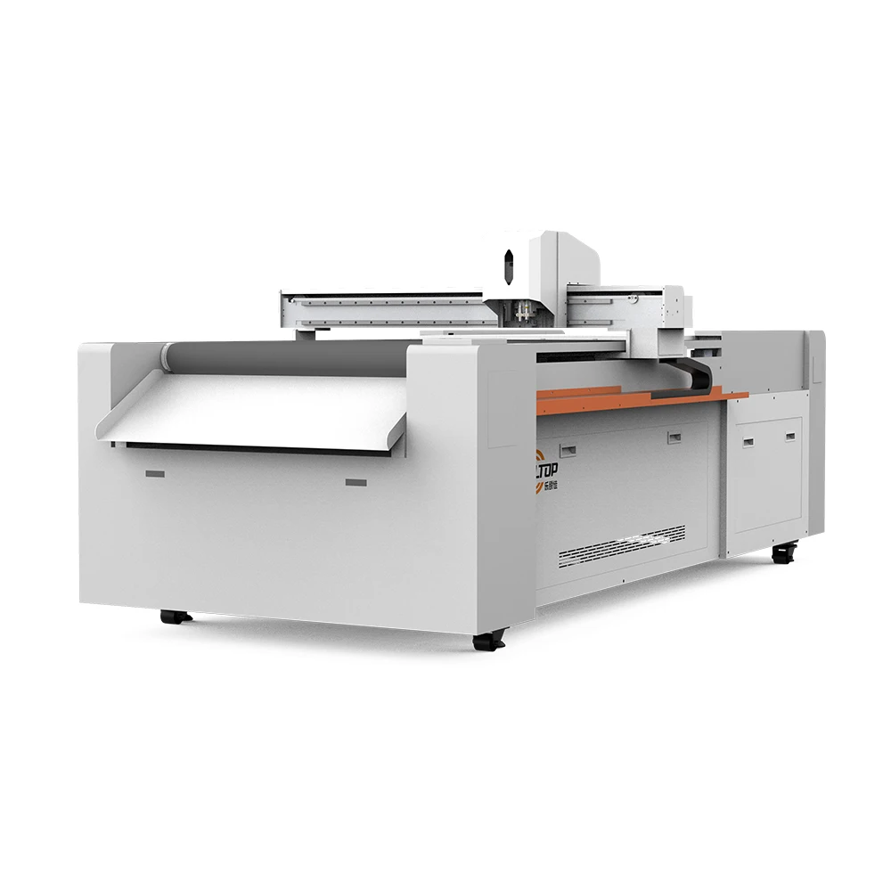
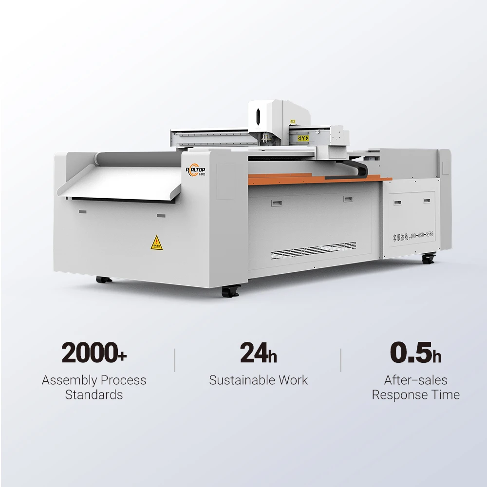
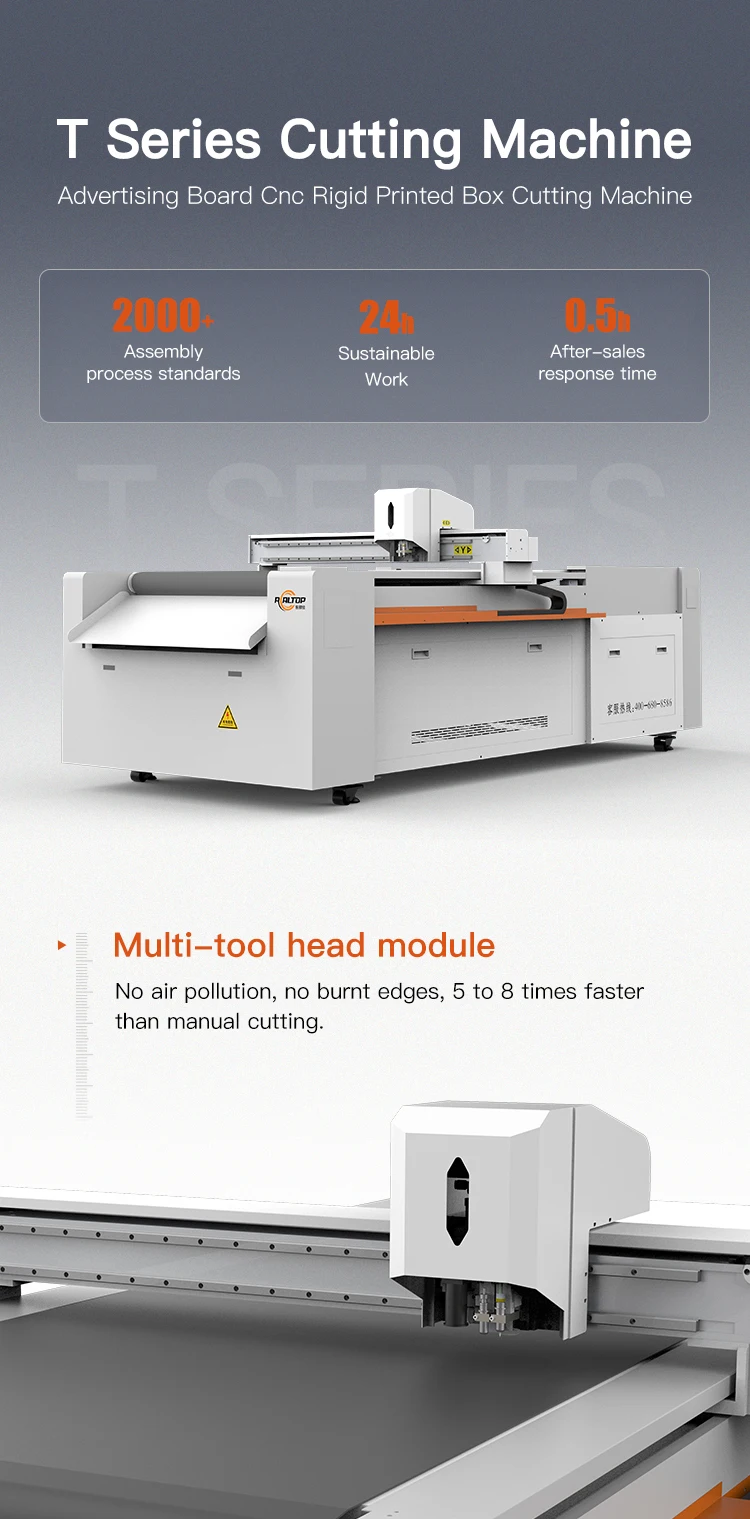
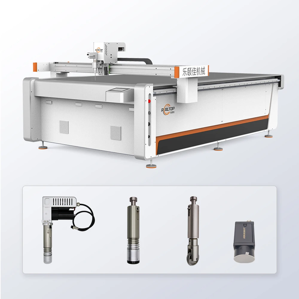
Configuration-Led Engineering — Each CNC flatbed cutting plotter is built around the buyer’s material, thickness and daily volume rather than a fixed catalogue spec, with tool head, vacuum zoning and CCD contour recognition confirmed on your own stock before order.
Technical Specifications
| Parameter | Value |
|---|---|
| Product Type | CNC Flatbed Digital Cutting Plotter |
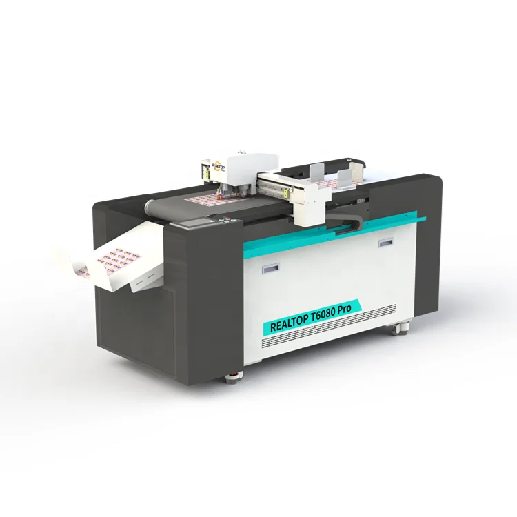
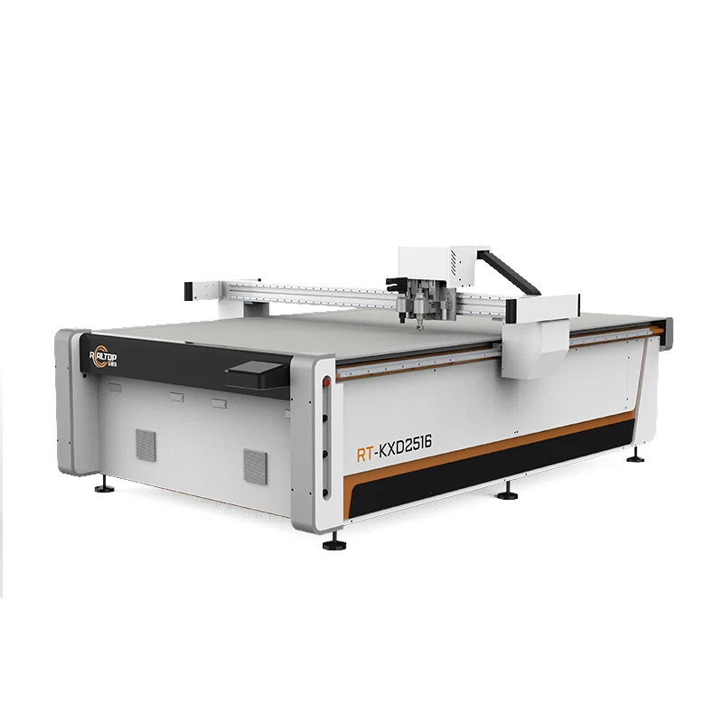
| Working Area Options | 400×600 mm / 600×800 mm / 900×1200 mm |
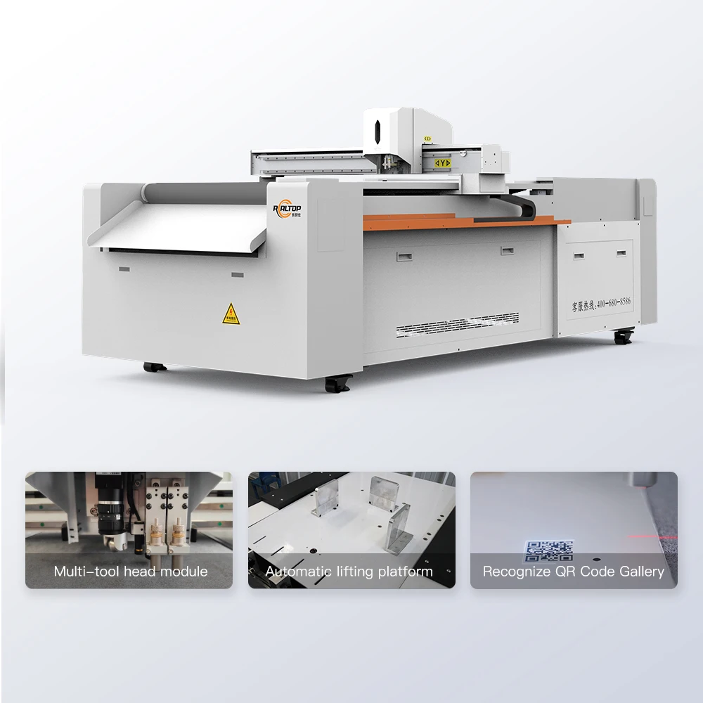
| Tool Head Options | Oscillating knife, Creasing wheel, Kiss cutting tool, CCD camera, Marking pen |
| Cutting Speed Range | 0–1500 mm/s |
| Cutting Thickness Capability | ≤ 20 mm (basis not stated in source) |
| Cutting Accuracy | ±0.1 mm |
| Vacuum Pump Rating | 2.5 kW / 3.2 kW |
| Operating Voltage | 110V / 220V |
| File Format Support | PLT, DXF, AI, PDF |
| Safety Devices | Infrared sensor and emergency stop |
| Software Language | English, Russian, Italian, Chinese (special languages customizable) |
| Positioning System | CCD camera auto-recognition of registration marks |
| Assembly State | Desktop / compact structure |
Application Suitability
| Application | Material or Output |
|---|---|
| Packaging and carton sample making | Corrugated board, greyboard, kraft paper for structural prototypes and short-run mock-ups |
| Advertising and signage production | Self-adhesive vinyl, heat transfer film, printed PVC board and window cling stock |
| Craft and cultural products | Cardstock, leather sheets, felt and thin foam for intricate contour work |
| Light industrial gaskets | Closed-cell foam, rubber sheet and non-woven gasket material in small batches |
| Educational templates | Laminated paper, thin plastic and magnetic sheet for teaching aids and puzzle sets |
Why a Working Area Spec Alone Fails at the Cutting Table
Buying a CNC flatbed cutting plotter manufacturer quote based only on table dimensions is a recurring source of production-floor disappointment. The cutting result depends far more on tool head selection, vacuum hold-down and actual material behaviour than on the X-Y travel envelope.
I have stood next to a carton sample table in the Gulf where the creasing wheel produced shallow scores because the board gsm was one layer heavier than the sample used during specification. The machine was dimensionally correct but configurationally wrong. The same pattern appears when a buyer switches from cast vinyl to calendared film without adjusting the kiss cutting tool depth or vacuum zone layout [NEED_CITE: flatbed cutting tool selection versus material behaviour]. Specifying the cutting method, tool head and vacuum zoning against your real stock eliminates this class of failure before the machine is built.
Design, Production and Integration Under One Roof
The cutting platform is developed and assembled by an in-house design team that controls both the knife tooling mechanics and the motion control stack. This matters when a packaging sample maker needs the creasing wheel calibrated against a specific flute profile, or a vinyl shop requires the CCD camera to track printed registration marks at production speed. Because the same engineering group handles mechanical and software integration, file format compatibility with AI, PLT, DXF and PDF workflows is confirmed before the CNC flatbed cutting plotter manufacturer accepts the order rather than discovered at commissioning.
How the CCD Camera Closes the Loop on Printed Contours
When a sign shop prints graphics onto vinyl and then needs to cut along the printed edge, manual alignment introduces drift that accumulates over a long production run. The CCD camera reads registration marks placed on the printed sheet and feeds offset corrections back to the motion controller in real time. This keeps contour accuracy within the ±0.1 mm specification across the full 900×1200 mm working area, which is the format most mid-volume packaging and graphics producers use. Registration mark size, contrast and placement are documented in the operation manual so operators can design artwork with recognition reliability in mind [NEED_CITE: CCD registration mark design guidelines for flatbed cutters].
Reading the Spec Sheet Against Your Production Reality
The three working area formats — 400×600 mm, 600×800 mm, and 900×1200 mm — correspond to different sheet stock sizes and shop floor footprints. A compact desktop unit suits a studio cutting leather bookmarks and craft cards, while the larger table accommodates full packaging sample sheets without repositioning. The 0–1500 mm/s cutting speed range is usable differently depending on tool head: an oscillating knife cutting 3 mm foam will run at a lower speed than a drag knife scoring thin vinyl, and the CCD contour loop introduces its own dwell time at each registration mark. Vacuum pump rating of 2.5 kW or 3.2 kW must be matched to the table zone layout; a small part nested near the centre of a large table needs sufficient local suction to prevent lift during the cut. Software language and voltage (110V or 220V) are locked in writing before production begins so the control interface and electrical cabinet match the destination market [NEED_CITE: industrial voltage and frequency standards by region].
The Hidden Cost of Skipping the Sample Cut
A machine that runs perfectly on the factory’s reference stock can behave differently on the buyer’s actual material. I recall a leather tag job where the oscillating knife left micro-tears on the flesh side because the material had a different backing coating than the test piece. The fix required a different blade angle and a slower pass speed — changes that would have been captured in a pre-order sample cutting report but were instead discovered after the machine arrived. Similar mismatches happen when vacuum zoning is too coarse for the smallest part in a nest, allowing lift that ruins edge quality and wastes material [NEED_CITE: vacuum hold-down zoning effects on small part cutting].
Why Buyers Source This CNC Flatbed Cutting Plotter Manufacturer
In-house design covers both knife and CCD-based cutting on a single platform, so a buyer can match the cutting method to the material rather than force one technology across all jobs. Tool head and table configuration are specified per material type and production volume, not left to a generic catalogue pick. CCD camera positioning is included and calibrated for printed contour work where the application demands it. Software compatibility with the buyer’s existing AI, PLT, DXF or PDF workflow is verified before order acceptance. Voltage, plug type and control language are confirmed in writing so the machine arrives ready for local power and operators.
Documentation & Verification
- Machine specification sheet listing every tool head and table configuration selected for your material
- Electrical schematic with voltage, frequency and plug type confirmed for your destination market
- Sample cutting report produced on your own stock with measured edge quality and thickness results
- Tool head and vacuum table configuration list detailing zones, pump rating and knife geometry
- Software licence and file format compatibility note covering AI, PLT, DXF and PDF import paths
- Factory test record with cutting accuracy measurement and CCD recognition cycle documentation
Installation, Commissioning & Support
- Level floor required; the compact desktop assembly can be placed on a reinforced bench for the 400×600 mm format
- Dedicated circuit matching the confirmed 110V or 220V supply with appropriate breaker rating for the vacuum pump load
- Pre-assembled frame with bolt-on gantry; two technicians can complete mechanical assembly on site
- First power-on includes vacuum zone mapping, CCD calibration on your printed sample and tool head depth setting
- Operator training covers file import, nesting, tool change and emergency stop procedures in the confirmed language
- Spare parts list covers oscillating knife blades, creasing wheels, vacuum cups and CCD illumination elements
- Scheduled maintenance intervals for linear guide lubrication, belt tension check and vacuum filter replacement
What to Include in Your Inquiry
Send the material type, thickness and maximum sheet size you plan to process, along with the daily volume and the file format your design team currently uses. Confirm the local voltage and frequency at your facility and the preferred control software language. If you already run a nesting or CAD workflow, provide a sample file so compatibility is checked before quotation.
Frequently Asked Questions
Q: How do I verify the cutting thickness the machine can actually handle?
A: The ≤ 20 mm figure depends on material density, tool head and feed speed. We run your actual stock on the factory table and issue a sample cutting report with measured edge quality and achievable depth, so you see the result on your material before committing.
Q: Which tool head fits my material — oscillating knife, drag knife or creasing wheel?
A: Oscillating knives suit thicker, fibrous or compressible materials like foam and corrugated board. Drag knives handle thin films and vinyl. Creasing wheels score fold lines on carton stock. We recommend and test the combination based on your sample.
Q: How are voltage, plug type and control language confirmed before shipment?
A: These are locked in writing during the specification confirmation stage. The electrical schematic shows the exact voltage, frequency and plug type, and the control interface is loaded with your chosen language before the factory test.
Q: Will the software work with my existing design files?
A: The platform imports PLT, DXF, AI and PDF formats. Before the order is finalised, we test your actual files through the nesting and cutting workflow to confirm that line weights, contour recognition and tool path generation behave as expected.
Q: Can I visit the factory and run a sample cut on my own stock?
A: Yes. Send your material to the factory or bring it in person. We mount it on the table, configure the tool head and vacuum zones, and produce a cutting sample with documented results so you can evaluate edge quality and throughput before purchase.
You may also like

商品评价
Clear filtersThere are no reviews yet.