



-
 Courier delivery
-
 DHL Courier delivery
-
 Warranty 1 year
-
 Free 30-Day returns

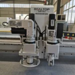
In-House Build Control — Frame machining, motion assembly and tool head calibration are handled under one roof for the 1070PAS4 A1, not outsourced to separate integrators.
Technical Specifications
| Parameter | Value |
|---|---|
| Model | 1070PAS4 A1 |
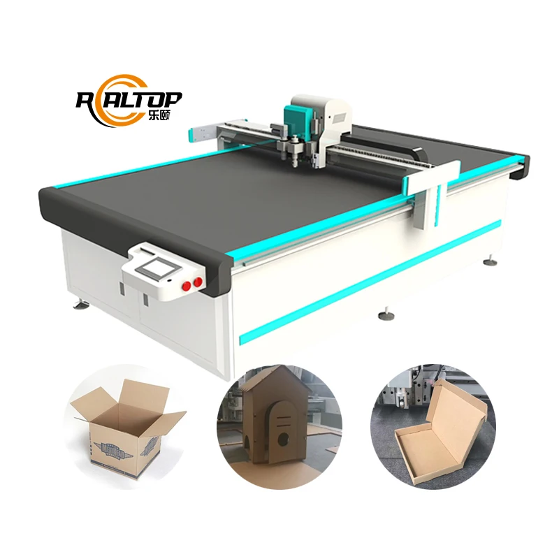
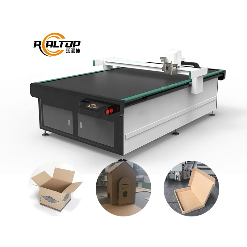
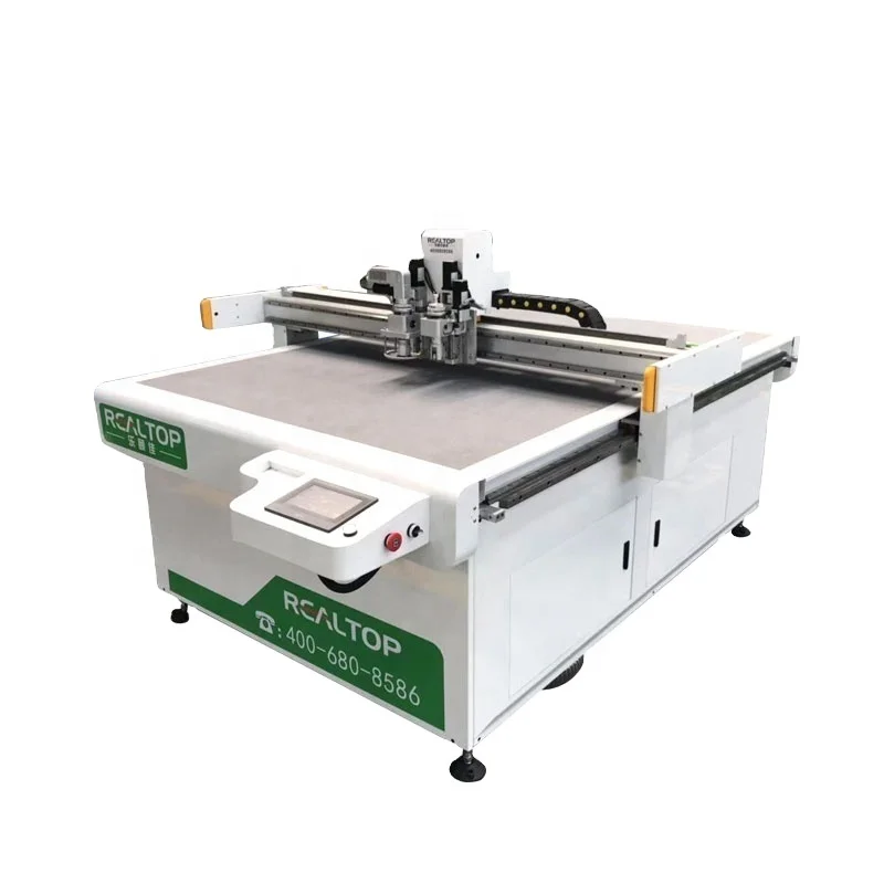
| Product Type | CNC Oscillating Knife Cutting Machine |
| Working Area | 400mm × 600mm |
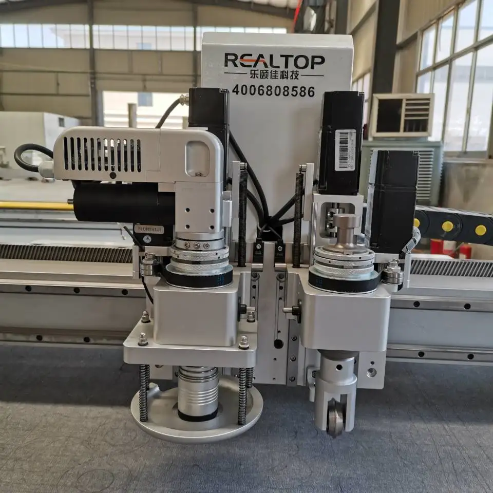
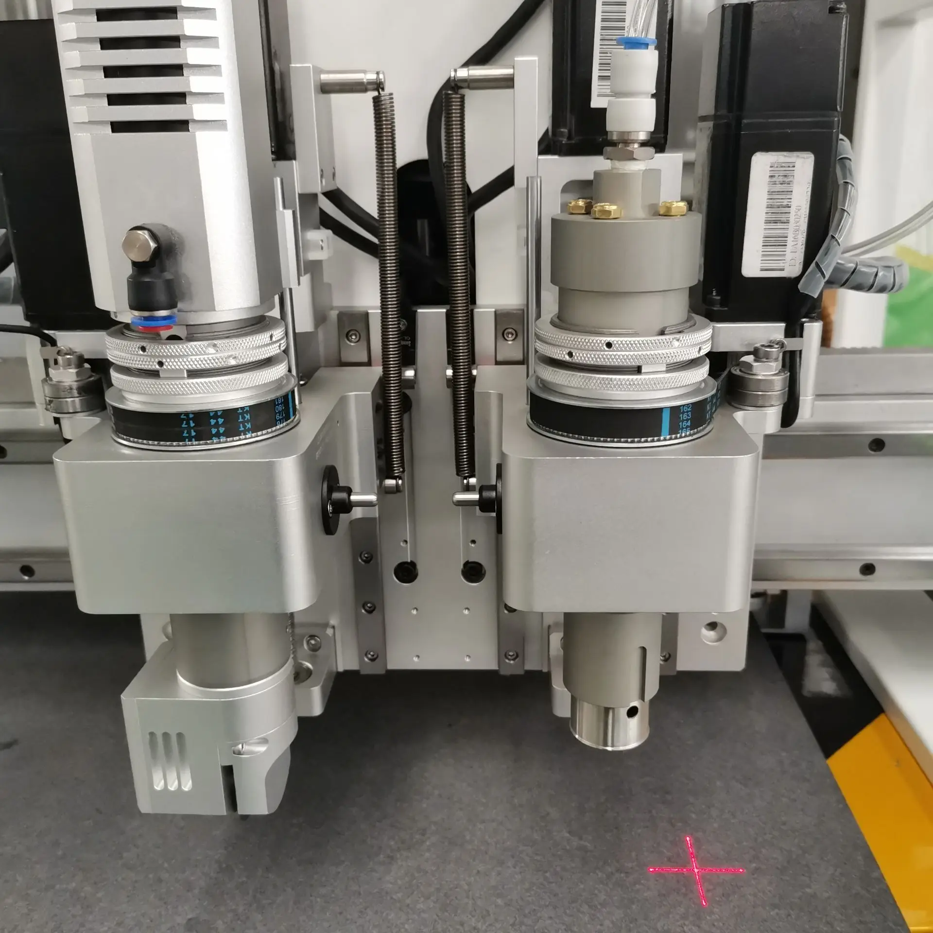
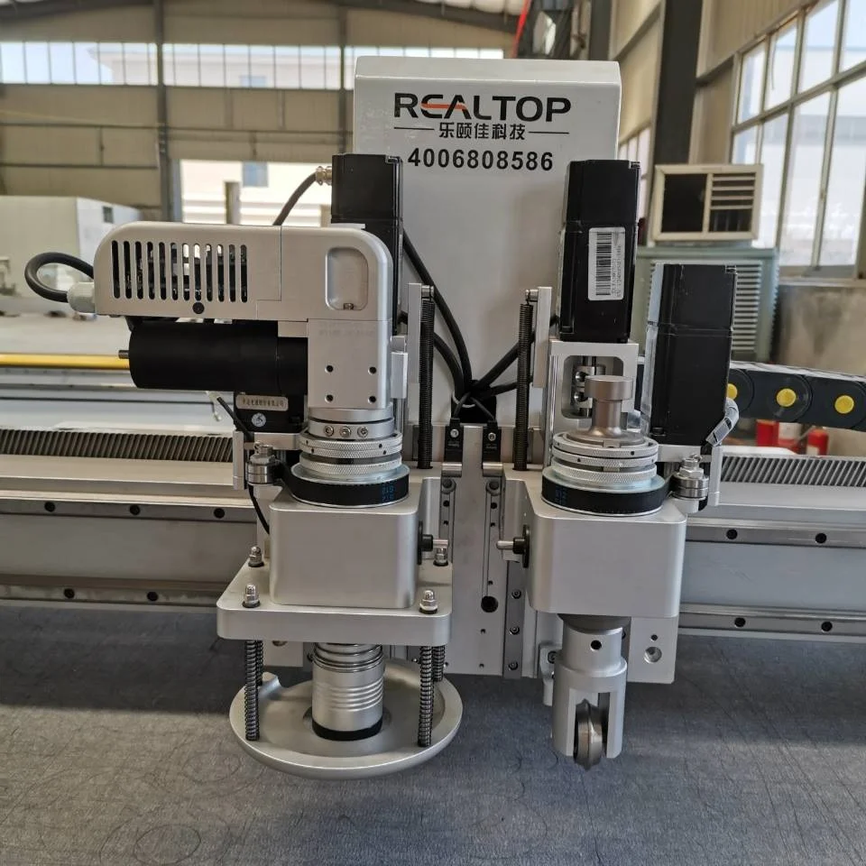
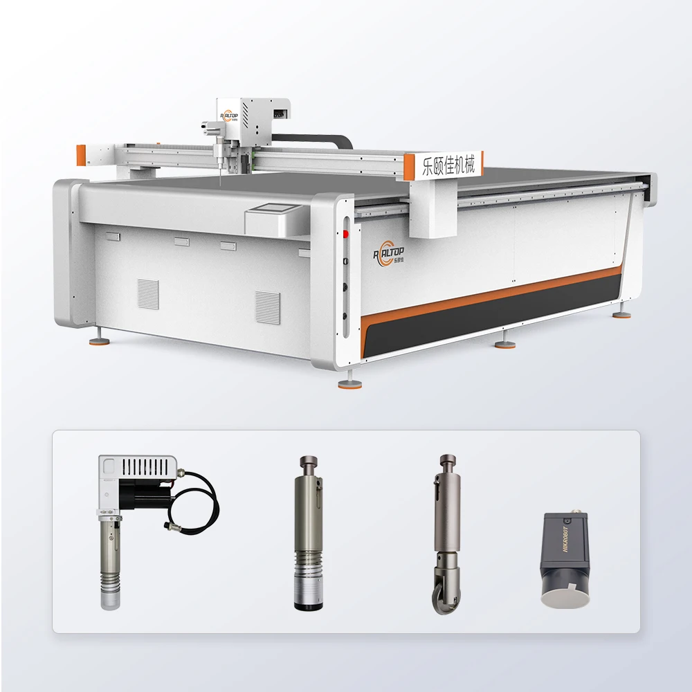
| Tool Head Options | Cutting Tool; Kiss-cutting Tool; Creasing Tool; CCD Camera; High Speed Oscillating Knife (Pro model only) |
| Max Cutting Speed | 1500mm/s (according to the material) |
| Cutting Thickness | <2mm (standard) / <5mm (Pro model) |
| Positioning Accuracy | 0.05mm |
| File Formats | DXF, OLT, PDF, AI |
| Transmission Method | Ethernet port |
| Rated Power | 2.5kW |
| Voltage & Frequency | Configurable per target market (basis to be confirmed) |
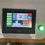
| Control System | CNC (specific controller brand basis to be confirmed) |
| Vacuum Zones | Configuration based on working area (basis to be confirmed) |
| Software & Nesting | Compatibility confirmed prior to order (basis to be confirmed) |
| Language Options | Control language customizable (basis to be confirmed) |
| Assembly State | Factory assembled and tested (basis to be confirmed) |
| Warranty | One year for whole machine |
Application Suitability
| Application | Material or Output |
|---|---|
| Packaging and Carton Sample Making | White card, grey board, corrugated board (cutting and creasing) |
| Leather Goods and Footwear | Natural hides, synthetic leather, PU/PVC sheets |
| Signage and Gasket Prototyping | Thin non-metal sheets, vinyl, adhesive films (kiss-cutting) |
Why "Working Area" Is Not Enough for a CNC Oscillating Knife Cutting Machine Manufacturer
Tool head selection must be locked to the actual material before the frame is ever welded.
A buyer often specifies a flatbed cutter based solely on table size, only to find the machine cannot handle the material thickness or density once it arrives. In my early days on the assembly floor in Jinan, we shipped a unit for carton sample making that was tested on standard white card. The customer’s actual stock was thick grey board with corrugated layers. The parameters failed completely, and it took three days on-site to recalibrate the tool pressure and oscillation frequency. That incident cemented our rule: the cutting method and tool configuration must be matched to the buyer’s specific material stack and daily volume [NEED_CITE: material density impact on knife cutting tooling].
Matching the Tool Head to the Material Stack
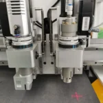
The 1070PAS4 A1 is configured with a specific tool head array based on what you are actually cutting. A drag knife might work for thin vinyl, but it will crush foam or leave ragged edges on thick corrugated board. By offering oscillating knife, kiss-cutting, and creasing tools within the same chassis, the machine can be set up to handle the exact transition between cutting a gasket outline and creasing a packaging fold line. This prevents the need for manual secondary operations that slow down the sample-making process.
The Role of CCD Positioning in Printed Contours
For packaging and signage producers, the CCD camera option is not just an add-on; it is the bridge between digital design and physical output. When a printed sheet is placed on the table, the camera recognizes the printed marks and adjusts the cutting path in real time. This is critical when the material has stretched or distorted during the printing process, ensuring the final sample or production piece maintains the required dimensional accuracy [NEED_CITE: CCD contour recognition in digital finishing workflows].
Understanding the 0.05mm Positioning Accuracy
In the context of packaging sample making and leather cutting, a positioning accuracy of 0.05mm ensures that creasing lines align perfectly with cut edges. If the tolerance drifts, a folding carton will not assemble square, or a leather pattern piece will not match the lasting template in footwear production. The Ethernet transmission method supports stable file transfer of complex DXF or AI vectors, preventing the data corruption that can occur with older serial connections in a busy design office environment.
The Cost of Ignoring Voltage and Zoning
A machine built for a 380V three-phase supply will suffer immediate component stress if connected to a 220V single-phase workshop line without proper transformation. Beyond the electrical mismatch, an insufficient vacuum table zoning configuration will cause small packaging parts to lift during high-speed oscillation, ruining the sample and potentially damaging the knife tip. These are failures that occur before the first week of production is over [NEED_CITE: electrical schematic and voltage confirmation standards].
Why Buyers Evaluate the Core Factory Build
When sourcing from a CNC oscillating knife cutting machine manufacturer, the focus should be on who controls the build quality. Our in-house design team oversees the frame stress-relief treatment and the linear motion component assembly. This means the machine geometry is verified by the same team that designed it, rather than a third-party assembler. We provide a factory test record that demonstrates the machine cutting your specific material, not a generic demo sheet.
Documentation & Verification
- Machine specification sheet detailing the exact tool head and vacuum zone layout for your material.
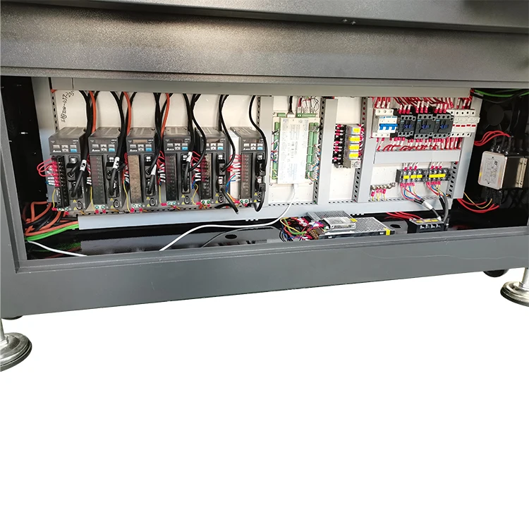
- Electrical schematic confirming voltage, frequency, and plug type for your local facility.
- Factory test record showing actual cut samples on your provided cardboard or leather stock.
- Operation and maintenance manual with software license and file format compatibility notes.
Installation, Commissioning & Support
- Foundation must be level to within 2mm across the 400mm × 600mm footprint to maintain gantry geometry.
- Dedicated circuit required for the 2.5kW rated power to prevent voltage drop during oscillation peaks.
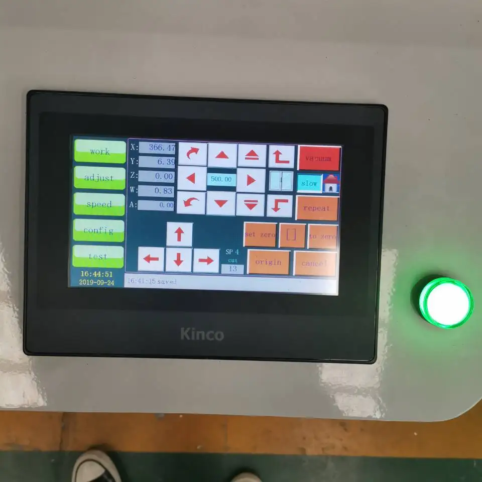
- Ethernet port setup and control language configuration verified during the first power-on sequence.
- Initial tool pressure and oscillation frequency calibration performed on your specific material thickness range.
- Spare parts list provided with a focus on consumable blades and oscillation bearings.
- Vacuum table zoning check to ensure adequate hold-down for your smallest sample part sizes.
Preparing Your Material for a Technical Audit
To get a precise configuration for the 1070PAS4 A1, provide the exact material type, maximum thickness, and sheet dimensions you intend to process. We also need to know your local voltage and frequency standards, as well as the primary file formats (DXF, PDF, AI) your design team uses. If you are working with printed materials, send a sample sheet so we can verify the CCD recognition capability before the machine enters the production queue.
Frequently Asked Questions
Q: How do I verify that the manufacturer actually builds the core components?
A: You should request a factory test record and a detailed electrical schematic. As a core factory, we provide documentation showing the frame machining origin and the specific motion components installed. This ensures the CNC oscillating knife cutting machine manufacturer you are dealing with controls the assembly process, rather than simply bolting together sourced modules.
Q: What is the process for matching the tool head to my material?
A: We require a sample of your actual material (e.g., grey board, corrugated, or leather) to conduct a cutting test. The results dictate which tool head (oscillating, drag, or creasing) and blade type are specified in the final configuration. This prevents the ragged edges or crushed layers that occur when a standard tool is forced onto a specialized material.
Q: How is voltage and software compatibility handled before shipping?
A: Before production begins, we confirm your facility’s voltage, frequency, and plug type through a formal electrical confirmation document. We also verify that the CNC control system supports your required file formats (DXF, OLT, PDF, AI) and that the control language matches your operator’s preference.
Q: Can the machine handle both packaging samples and thin gasket materials?
A: Yes, provided the tool head array is specified correctly. The 1070PAS4 A1 can be equipped with a creasing wheel for cardboard and a cutting tool for thin non-metal gaskets. The configuration is finalized during the inquiry stage based on your daily production mix and the maximum thickness of each material type.
You may also like

商品评价
Clear filtersThere are no reviews yet.