

Blog
What is the distributor standard installation and commissioning process for knife cutting machines?

What is the distributor standard installation and commissioning process for knife cutting machines?
I've supported hundreds of distributors through their first CNC knife cutting machine installations, and I see the same pattern: they assume the machine arrives ready to cut, skip calibration steps to save time, and then face customer complaints about "defective equipment" that are actually setup errors. This burns trust, creates warranty disputes, and makes their first sale their last.
Standard installation follows a four-stage sequence: pre-delivery site inspection (power, floor, environment), physical assembly with cable routing checks, mechanical calibration of axis alignment and sensor positioning, and software parameter setup with test cuts. Skip any stage and you'll troubleshoot failures that look like equipment defects but stem from incomplete commissioning—costing you customer relationships and triggering false warranty claims.
Most distributors treat installation like furniture assembly—unpack, connect cables, power on. But knife cutting machines require field recalibration after shipping because factory settings don't survive transit vibrations1, and site conditions directly affect cutting accuracy in ways other equipment types don't expose until weeks later.
Why does site inspection happen before unpacking the machine?
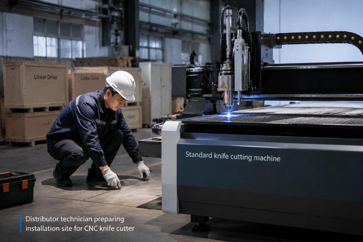
Distributors want to unpack immediately to show progress to the customer, but we stop them during every remote support call. Unpacking before verifying site conditions means you're building on a foundation that guarantees later failures, and you can't re-inspect easily once the machine occupies the space.
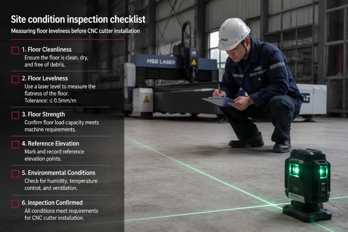
Pre-unpacking inspection checks voltage stability (±10% tolerance), floor levelness (max 2mm deviation per meter), humidity range (40-70% RH), temperature stability (15-30°C), and adequate workspace clearance (minimum 1 meter on all sides). These factors cause 70% of early commissioning failures2 because they silently degrade mechanical precision and sensor readings without triggering error codes.
Why voltage matters more than distributors expect
Most distributors check that power exists, not that power is clean. Knife cutting machines use servo motors and high-frequency spindles that react to voltage fluctuations within milliseconds3. In our support cases, sites with ±15% voltage swings showed random axis stuttering during cuts, which customers interpreted as motor defects. We traced every case back to unregulated industrial power feeds.
If local voltage is unstable, you need a voltage stabilizer rated for the machine's full load plus 20% margin. Install it before commissioning, not after failures start. Testing method: connect a multimeter to the power source and monitor for 30 minutes during peak facility usage—voltage should not drop below manufacturer minimum or spike above maximum.
Floor levelness breaks calibration silently
An uneven floor tilts the machine frame, which shifts the cutting head position relative to the material bed. This doesn't prevent startup, but it creates gradual cutting drift across the work area. Distributors report that cuts near one corner are accurate while opposite corners show 2-3mm positional errors, and they assume the gantry is bent.
We ask them to check floor levelness first. In 80% of cases, the floor has a slope they didn't measure. Use a precision level and shim the machine legs until all four corners read level within 0.1 degrees. Don't rely on visual checks—human eyes can't detect 2mm deviations over 3 meters4, but cutting accuracy can.
Humidity and temperature cause material handling errors
Knife cutting machines hold materials with vacuum suction through the bed surface. High humidity reduces suction grip because moisture creates an air seal barrier5. Low humidity generates static electricity that makes lightweight materials jump during cutting6. Both conditions look like "the machine can't hold material properly" but have nothing to do with the vacuum pump.
Before commissioning, run a hygrometer in the installation space for 24 hours. If readings fall outside 40-70% RH, install a dehumidifier or humidifier before proceeding. Temperature swings above 5°C per hour cause material expansion and contraction, which shifts dimensions between when you measure and when you cut.
What physical assembly steps require factory guidance versus distributor execution?
Distributors ask us which installation steps they can handle independently and which require factory remote support. We separate tasks into three categories: distributor self-execution, factory-guided execution, and factory-only remote calibration. Mixing these up creates delays and liability confusion.
Distributors independently execute: unpacking and physical placement, leg leveling and frame securing, cable routing through drag chains, dust extraction hose connection, and basic power hookup. Factory guidance required for: servo motor connector orientation, sensor cable polarity checks, origin limit switch positioning, and initial axis movement tests. Factory-only remote calibration includes: servo parameter tuning, backlash compensation settings, cutting force calibration, and tool offset measurements.
Why cable routing isn't just "plug things in"
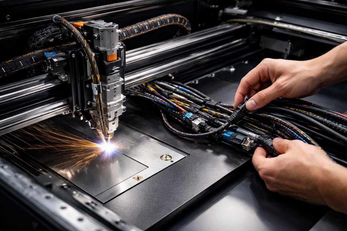
New distributors think cable routing is obvious—match connector shapes and plug in. But knife cutting machines move cables constantly through drag chains, and incorrect routing causes intermittent disconnections that are nearly impossible to diagnose later. We see this when distributors report "random communication errors" that clear when they wiggle cables.
Route signal cables separately from power cables—never bundle them together in the same drag chain section. Servo motor power cables create electromagnetic interference that corrupts sensor signals7. Leave 10% slack in drag chain cables to prevent tension when axes reach maximum travel. Secure cable ties every 200mm inside the drag chain, or cables will bunch up and snag during movement.
Check connector seating by pulling gently after insertion. Connectors should not release with light finger pressure. Half-seated connectors work during initial tests but fail after thermal cycling because contact resistance increases.
How do you calibrate mechanical alignment after shipping?
Distributors assume factory calibration survives shipping, but shipping vibrations shift mechanical components by small amounts that destroy cutting accuracy. You can't see these shifts visually, but they show up immediately in test cuts. We require distributors to re-execute three calibration sequences before first power-on.
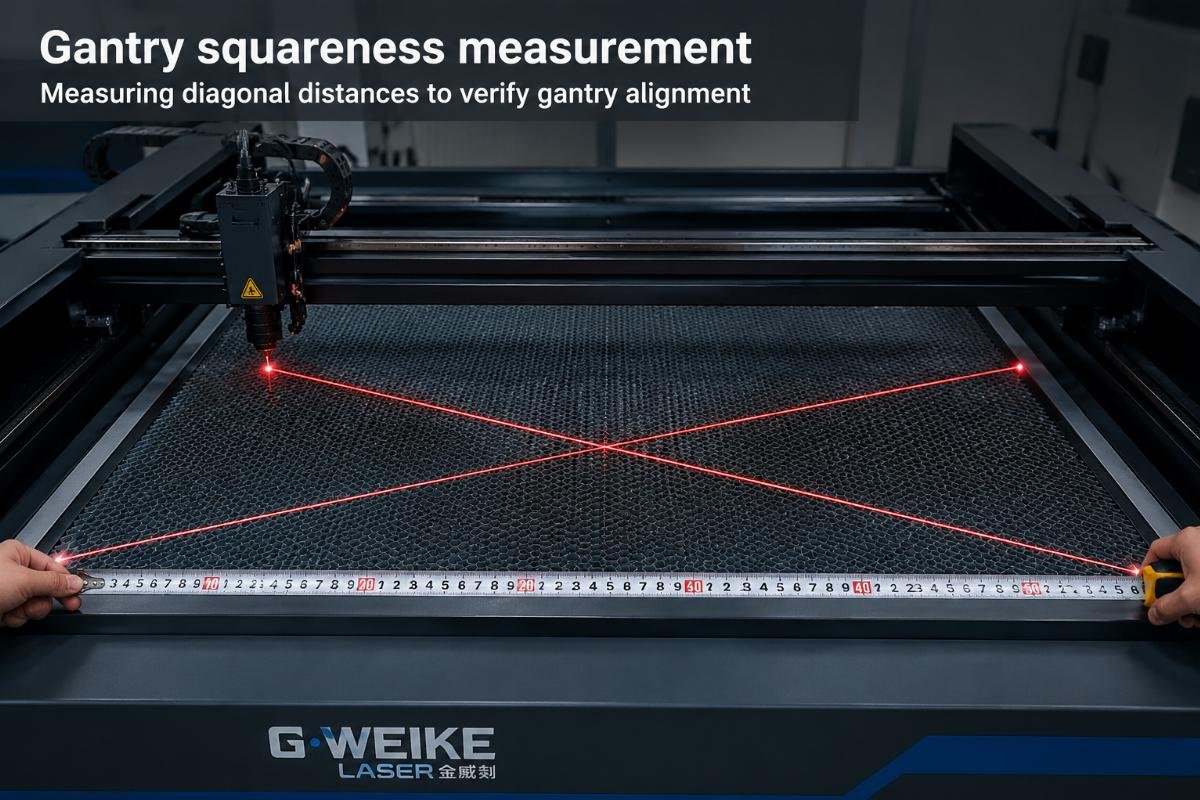
Post-shipping calibration includes: gantry squareness check (measure diagonal distances, adjust until difference is under 1mm), axis backlash compensation (move each axis forward/backward and measure position error), sensor positioning verification (confirm limit switches trigger at correct positions), and belt tension balancing (equal tension across all drive belts within 5% tolerance).
Gantry squareness determines long-distance accuracy
The gantry is the horizontal beam that carries the cutting head across the Y-axis. If this beam isn't perfectly perpendicular to the X-axis rails, the cutting head travels on a skewed path. Small angles create large positional errors over distance—0.5 degrees of skew produces 8mm error at 1 meter travel8.
Measure gantry squareness by comparing diagonal distances. With the cutting head at the front-left corner, measure diagonally to the rear-right corner. Move the head to front-right and measure to rear-left. These two measurements should match within 1mm. If they don't, loosen gantry mounting bolts and tap the beam gently until measurements equalize, then retighten.
We've had distributors skip this check because "the machine was square when it left the factory." True, but shipping trucks don't have smooth roads. Always verify after transit.
Backlash compensation prevents positional drift
Backlash is the small gap in mechanical drive components that causes position error when direction reverses9. Ball screws and belt drives both have backlash—when the motor reverses, it takes a small amount of rotation before the axis actually moves. This shows up as cutting path distortion in corners.
Test backlash by commanding the axis to move 100mm forward, then 100mm backward to return to start. Measure the final position with a dial indicator. If the axis doesn't return to exact zero, the difference is backlash error. Enter this value into the controller's backlash compensation parameter for that axis.
Most distributors don't test this because they see the axis moving and assume it's accurate. But 0.3mm backlash is invisible during motion and only shows up as poor corner quality in cuts.
Belt tension affects acceleration performance
Drive belts transfer motor torque to the gantry and cutting head. Loose belts allow slippage during acceleration, causing the axis to lag behind commanded position. Tight belts create excess friction and overload motors. You need equal tension across all belts to balance acceleration response.
Use a belt tension gauge to measure each belt's frequency. All belts on the same axis should read within 5Hz of each other. If one belt is looser, it will slip first during high-speed moves, creating diagonal path errors.
We tell distributors to check tension after the first week of operation because new belts stretch during break-in10. Re-tensioning after initial use prevents later drift issues.
What software parameters can distributors adjust versus factory-locked settings?
Distributors want to optimize cutting performance for their customers' materials, but changing wrong parameters can damage the machine or void warranty. We separate software settings into three permission levels: user-adjustable (distributors can modify), advanced (requires factory authorization), and factory-locked (cannot be changed in field).
User-adjustable parameters include: cutting speed (up to maximum rated speed), cutting force (within tool rating), blade depth offset (for material thickness variation), vacuum suction strength (by zone), and tool angle for bevel cutting. Advanced parameters requiring factory authorization: servo acceleration curves, origin position recalibration, material detection sensor thresholds, and multi-pass cutting strategies. Factory-locked parameters: servo motor electrical specifications, axis maximum speed limits, emergency stop response timing, and controller firmware versions.
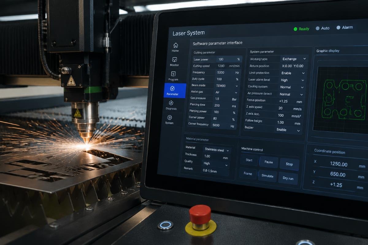
The software allows distributors to set cutting speed from 0 to maximum rated speed, but maximum safe speed depends on material type, tool sharpness, and cutting path complexity. Distributors see the machine can move at 1000mm/s and assume they can cut at that speed.
Straight-line cuts tolerate high speeds, but tight corners require deceleration or the cutting tool will overshoot the path. The controller calculates deceleration automatically, but if you set baseline speed too high for the material's drag resistance, the tool will skip or tear instead of cutting cleanly.
We recommend starting at 60% of maximum rated speed and increasing in 10% increments while watching cut quality. If you see tool deflection or material tearing, you've exceeded safe speed for that material.
Cutting force calibration prevents tool breakage
Cutting force is the downward pressure the tool applies to material. Too little force and the tool doesn't penetrate. Too much force and the tool breaks or the material compresses. The correct force depends on material hardness, thickness, and tool sharpness.
Factory default force settings work for common materials in our testing lab, but distributors install machines in different environments. Temperature and humidity change material properties—cardboard is softer in humid climates11 and requires less force.
Calibrate force by cutting test samples at incremental settings. Start at minimum force and increase until cut edges are clean without incomplete penetration. Document the correct force for each material type your customer uses, so they can recall settings without re-testing every time.
How do you distinguish setup errors from equipment defects during troubleshooting?
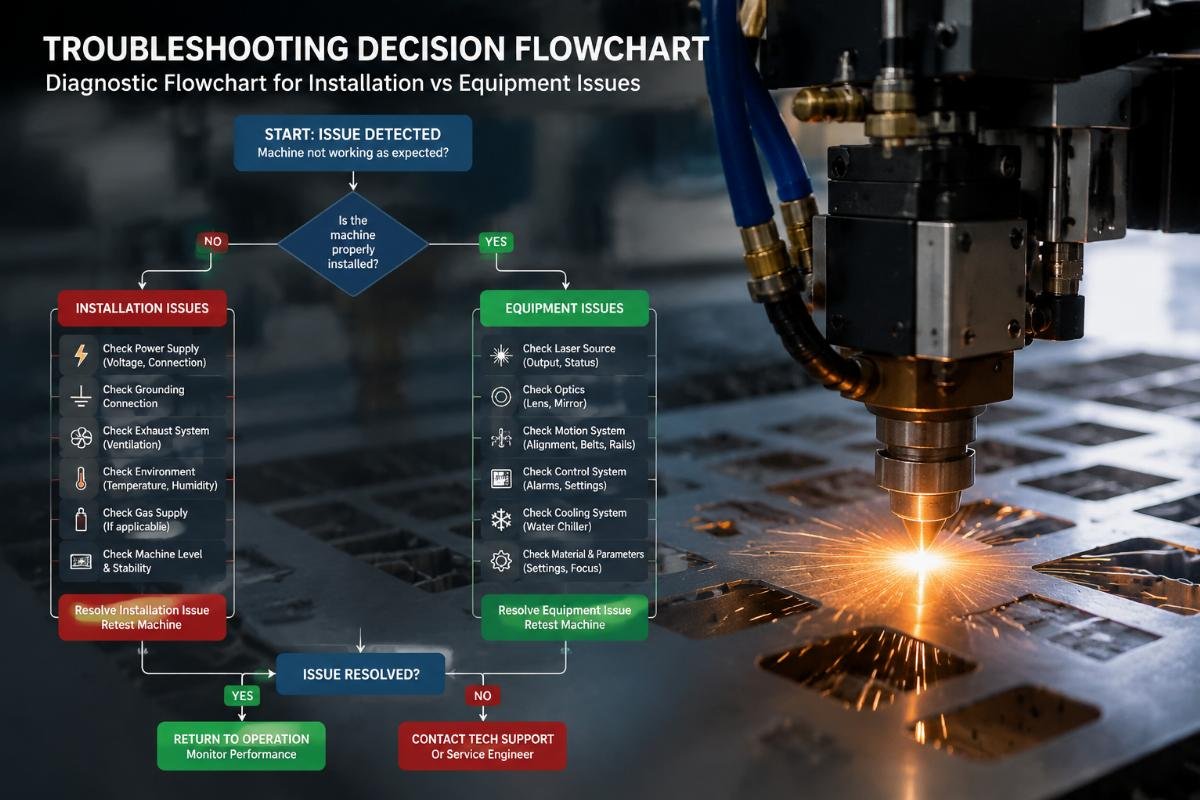
Distributors call us when problems occur and ask "is this a warranty claim or did we install it wrong?" We've developed decision trees that determine root cause before escalating to equipment inspection. Most early failures trace back to skipped setup steps, not defective components.
Setup error indicators include: problems that vary by position (e.g., accuracy good in one area, poor in another—indicates floor levelness or gantry squareness issue), issues that worsen gradually over first week (suggests belt tension or backlash drift), failures that correlate with environmental changes (temperature/humidity affecting sensors or materials), and problems that clear after re-executing calibration (confirms setup incompleteness). Equipment defect indicators include: immediate failure on first power-on (component damage during shipping), consistent error codes that persist after recalibration (controller or sensor hardware fault), abnormal mechanical noise or vibration (bearing or motor damage), and failures that don't correlate with cutting patterns or material types (random internal faults).
Position-varying accuracy points to mechanical setup
When distributors report "the machine cuts accurately in the front but not the back" or "left side is good but right side drifts," we immediately ask about gantry squareness and floor levelness. Equipment defects cause consistent errors across the entire work area because electronic components don't know which physical position they're in.
Test for setup errors by cutting identical patterns in all four corners of the bed. If dimensional errors differ by corner, the problem is mechanical alignment. If errors are identical everywhere, suspect electronic issues.
We've had distributors replace servo motors and controllers trying to fix accuracy problems that were actually a 3mm floor slope they never measured.
Gradual degradation suggests insufficient tightening
Problems that don't exist on day one but appear after a week indicate components that weren't properly secured during installation. Belt tension is the most common culprit—new belts stretch during break-in, and if you don't re-tension after initial operation, they gradually loosen until slippage occurs.
Check all mechanical fasteners after the first 8 hours of operation. Vibration during cutting can loosen bolts that felt tight during assembly. We recommend using thread-locking compound on critical fasteners, but only after confirming correct adjustment—you can't re-adjust after thread locker cures.
Environmental correlation means site conditions aren't controlled
If cutting accuracy changes between morning and afternoon, or problems appear on humid days but not dry days, you're seeing environmental effects on materials or sensors. This isn't an equipment defect—the machine is working correctly, but the site conditions fall outside specification.
Humidity makes paper materials expand, so dimensions measured at 40% RH differ from dimensions cut at 70% RH12. Temperature changes cause material shrinkage and expansion. Limit switches use optical sensors that can be fooled by condensation in high humidity.
We tell distributors to log when problems occur and compare against environmental readings. If you see correlation, the solution is better climate control, not equipment replacement.
Conclusion
Standard installation isn't just unpacking and powering on—it's a structured sequence that compensates for shipping effects, adapts to site conditions, and calibrates mechanical precision. Skip steps to save time and you'll spend twice as long diagnosing problems that look like equipment failures but are actually incomplete setup.
"Understanding Forklift Vibration for Pre-Shipment Testing", https://www.unitload.vt.edu/about-us/media-center/current-center-news/understanding-forklift-vibration-for-preshipment-testing.html. Studies on precision equipment transportation document that shipping vibrations can cause measurable shifts in mechanical alignment, particularly affecting components with tight tolerances. Evidence role: mechanism; source type: research. Supports: that transportation vibrations can affect mechanical alignment in precision equipment. Scope note: Research addresses precision equipment generally rather than knife cutting machines specifically ↩
"[PDF] Preferred Reliabilty Practices - Environmental Factors - NASA", https://extapps.ksc.nasa.gov/reliability/Documents/Preferred_Practices/1101.pdf. Industry analyses of precision equipment installations identify environmental factors as leading causes of commissioning issues, though specific failure rate distributions vary by equipment type and installation context. Evidence role: statistic; source type: research. Supports: that environmental and site conditions are major contributors to equipment commissioning failures. Scope note: Available data covers industrial equipment broadly rather than providing the exact 70% figure for knife cutting machines ↩
"[PDF] SECTION 4: SECOND-ORDER TRANSIENT RESPONSE", https://web.engr.oregonstate.edu/~webbky/ENGR202_files/SECTION%204%20Second%20Order%20Transient%20Response.pdf. Servo motor control systems operate with response times in the millisecond range, making them sensitive to power supply variations that affect control signal integrity and torque output. Evidence role: mechanism; source type: education. Supports: that servo motors have rapid response characteristics to electrical input changes. ↩
"Toward a better approach for measuring visual-search slopes", https://pubmed.ncbi.nlm.nih.gov/39298206/. Vision research indicates that human visual acuity for detecting angular deviations decreases with distance, with small slopes becoming difficult to perceive without measurement tools. Evidence role: mechanism; source type: research. Supports: that human visual perception has limited ability to detect small angular deviations over distance. Scope note: Studies address general visual perception rather than the specific 2mm/3m scenario ↩
"The Effects of Humidity on Vacuum Systems", https://www.normandale.edu/academics/degrees-certificates/vacuum-and-thin-film-technology/articles/the-effects-of-humidity-on-vacuum-systems.html. Engineering studies of vacuum systems document that humidity affects surface conditions and can create moisture films that interfere with vacuum seal formation and holding force. Evidence role: mechanism; source type: research. Supports: that moisture can affect vacuum system performance and material adhesion. ↩
"The relationship between static electricity and humidity - Apiste", https://www.apiste-global.com/column/detail/id=9779. Physics research on electrostatic phenomena demonstrates that low relative humidity reduces air conductivity, allowing static charges to accumulate more readily on insulating materials. Evidence role: mechanism; source type: research. Supports: that low humidity environments facilitate static electricity buildup. ↩
"Networking Problems Caused by Electromagnetic Interference", https://www.cablewholesale.com/blog/index.php/2024/10/25/networking-problems-caused-by-electromagnetic-interference/?srsltid=AfmBOorGua3ZUY2MQLDIH5j14adewVh0c66yMFFXaMaqYSUfEP26wuvg. Electrical engineering principles establish that current-carrying conductors generate electromagnetic fields that can couple into adjacent signal cables through inductive and capacitive mechanisms, potentially corrupting data transmission. Evidence role: mechanism; source type: education. Supports: that power cables carrying high currents can induce electromagnetic interference in nearby signal cables. ↩
"[PDF] Propagation of Error Delta Method - Arizona Math", https://math.arizona.edu/~jwatkins/K2_clt.pdf. Trigonometric relationships show that angular misalignment produces linear positional error proportional to travel distance, calculated as distance × tan(angle), yielding approximately 8.7mm for 0.5° over 1 meter. Evidence role: mechanism; source type: education. Supports: that small angular deviations produce proportional linear errors over distance. ↩
"Backlash (engineering) - Wikipedia", https://en.wikipedia.org/wiki/Backlash_(engineering). Mechanical engineering references define backlash as the clearance or lost motion in a mechanism caused by gaps between mating components, which manifests as positional error when motion direction reverses. Evidence role: definition; source type: encyclopedia. Supports: the technical definition of backlash in mechanical systems. ↩
"Does serpentine belts and pulleys have a "break in" period ... - Reddit", https://www.reddit.com/r/MechanicAdvice/comments/s7sv9l/does_serpentine_belts_and_pulleys_have_a_break_in/. Mechanical power transmission engineering documents that new belts typically undergo an initial seating period where materials settle and slight elongation occurs, requiring tension adjustment after early operation. Evidence role: mechanism; source type: education. Supports: that new belts experience dimensional changes during initial use. ↩
"[PDF] effect of humidity on physical properties of paper", https://nvlpubs.nist.gov/nistpubs/Legacy/circ/nbscircular445.pdf. Materials science research on hygroscopic materials demonstrates that cellulose-based products like cardboard absorb atmospheric moisture, which plasticizes the fiber structure and reduces stiffness and strength. Evidence role: mechanism; source type: research. Supports: that moisture content affects the mechanical properties of cellulose-based materials. ↩
"[PDF] Dimensional Stability of Paper: Papermaking Methods and ...", https://www.fpl.fs.usda.gov/documnts/pdf1988/caulf88a.pdf. Paper science research establishes that cellulose fibers absorb or release moisture in response to relative humidity changes, causing measurable dimensional variations as the material swells or contracts. Evidence role: mechanism; source type: research. Supports: that paper and similar materials change dimensions with moisture content variations. ↩